
Look beyond transmittance to scattering and detail
Transmittance is the ratio of transmitted luminous flux to incident luminous flux. Haze describes the proportion of transmitted light scattered through relatively large angles, while clarity concerns how clearly details can be seen through a material. These describe the amount of light, a milky appearance and image edges, respectively; they are not interchangeable.[1]
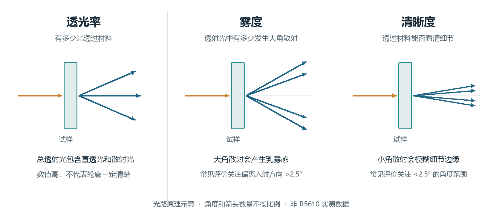
- Transmittance: how much light passes through the material.
- Haze: large-angle scattering, commonly measured at deviations greater than 2.5°; clarity: definition of details and edges, related to small-angle scattering. A cutoff below 2.5° is not a universal clarity formula.
- Specimen; directly transmitted light; scattered light.
- The light paths, angles and number of rays are schematic and not to scale; this is not a measurement of R-5610.
Common haze measurements consider transmitted light scattered more than 2.5° from the incident direction. Small-angle scattering is closely related to clarity. Numerical values must still be tied to the instrument and method; the fraction of light within 2.5° must not be treated as a universal formula for clarity.
For automotive interiors, preserving the base color and texture, creating uniform transmitted ambient lighting and displaying a sharp backlit pattern are different optical tasks. Define the objective before selecting measures such as transmittance, haze, color difference and pattern-edge definition.
How polymer-chain arrangement affects optical uniformity
Polymer chains may exist in a coiled, entangled amorphous state or form local crystalline regions with a more ordered arrangement. Crystalline and amorphous regions generally coexist in semicrystalline materials and may differ in density, orientation and optical properties. Light can scatter as it passes through these nonuniform regions.
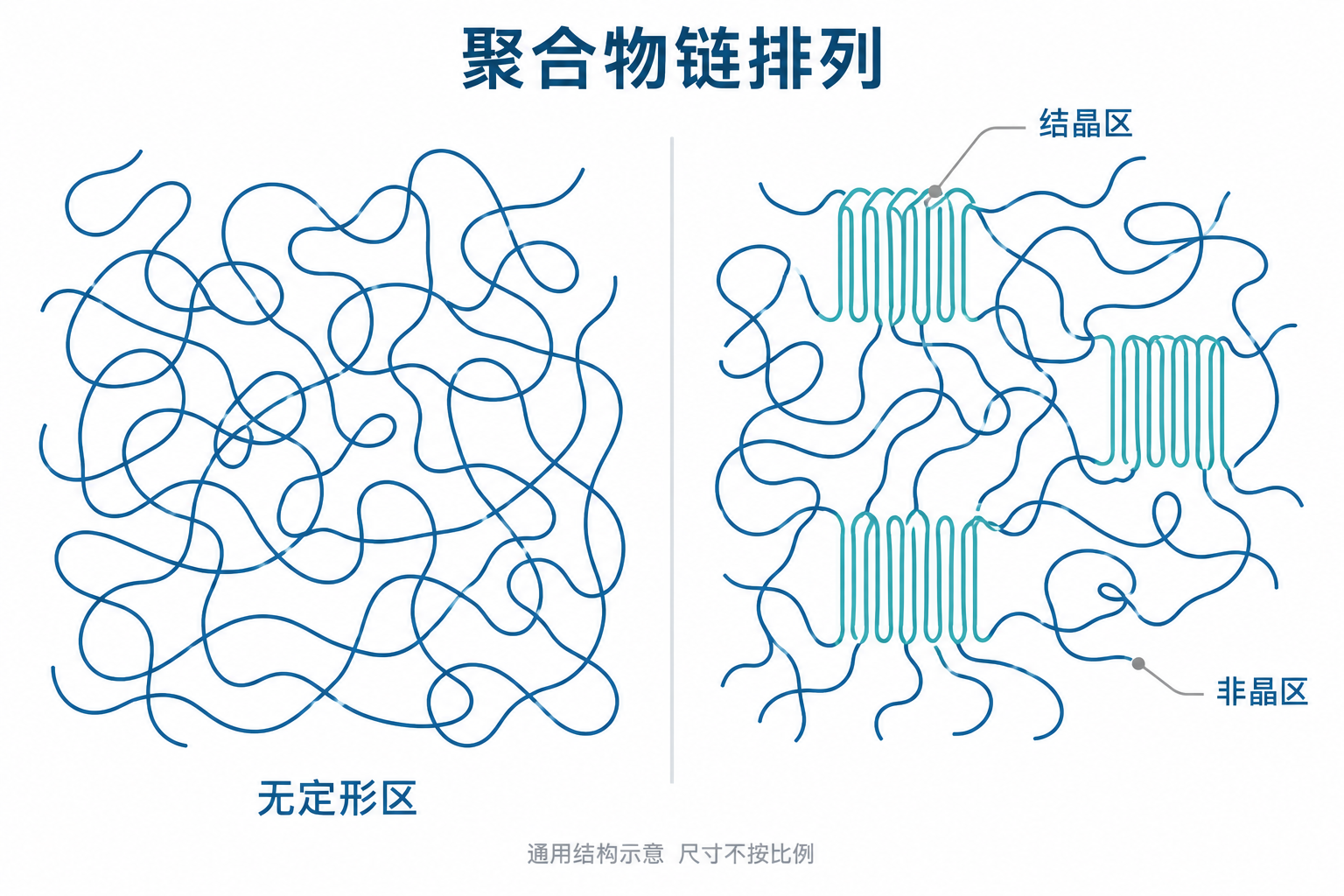
- Amorphous region; crystalline region; amorphous region alongside the crystalline region.
- General illustration of polymer-chain arrangements, not to scale; it does not represent a measured R-5610 microstructure.
Consider both structural dimensions and refractive-index differences
Scattering depends on the size and number of nonuniform regions, refractive-index differences and the distance light travels through the material. Larger structural differences, voids or incompatible dispersed phases can increase visible scattering. Greater thickness can also make the cumulative effects of absorption and scattering more pronounced.
Transparency cannot be ranked by crystallinity alone. Semicrystalline polymers can also achieve good transparency when crystal morphology and spherulite size are appropriately controlled, local refractive-index differences are reduced and surface condition is improved. Low haze observed in research often results from several structural factors acting together, rather than from a single crystallinity value.[2]
In bonding engineering, this principle means examining both the bulk adhesive film and any particles, voids or local nonuniformity within it. The intrinsic transparency of a resin cannot compensate for defects introduced during specimen preparation.
How polyurethane soft and hard segments balance transparency and bonding
A typical segmented polyurethane consists of chain segments with different mobilities. Flexible segments support deformation and interfacial contact. Hard-segment-rich microdomains and physical interactions such as hydrogen bonding can provide cohesion and load-bearing capacity. Segment compatibility, molecular weight and thermal history affect the formation and distribution of these domains.
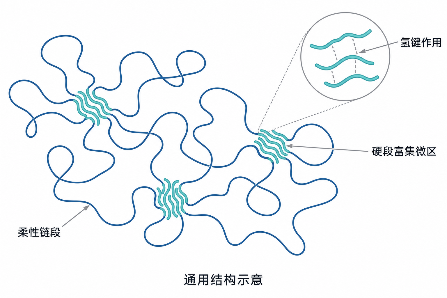
- Flexible segments; hard-segment-rich microdomains; hydrogen-bonding interactions.
- This illustrates a general physical structure. Hard-segment-rich microdomains are not equivalent to chemical crosslinking points.
- The illustration is not to scale and does not represent a measured R-5610 microstructure.
Microphase structure does not necessarily cause visible whitening
The presence of microphase structure in polyurethane does not mean that its film will necessarily be hazy. Visible-light scattering can only be assessed by considering domain dimensions, refractive-index differences, crystalline state and film thickness together. Light-scattering research also indicates that larger-scale nonuniform structures and density fluctuations within polyurethane need to be considered.[3]
Developing a light-transmitting adhesive system requires balancing chain mobility, cohesive strength and optical uniformity. Increasing hard-segment content or crosslinking does not guarantee simultaneous improvements in strength and transparency. If chain mobility is restricted too early, particle contact and the completeness of film formation may also be affected.
Structural analysis can combine thermal analysis, infrared spectroscopy and morphological characterization. Thermal analysis helps reveal transitions and crystallization; infrared spectroscopy provides clues about functional groups and hydrogen-bonding environments; microscopy or scattering methods reveal morphological differences. A transmittance or haze reading alone cannot identify a specific formulation or microdomain structure.
From a milky aqueous dispersion to a continuous adhesive film
In a waterborne polyurethane dispersion, polymer particles are distributed throughout an aqueous phase. Optical differences between the particles and the water cause scattering, so the wet adhesive may appear milky white. Transparency after drying depends on whether water removal allows a continuous, uniform polymer film with few defects to form. It cannot be judged solely from the color in the container.
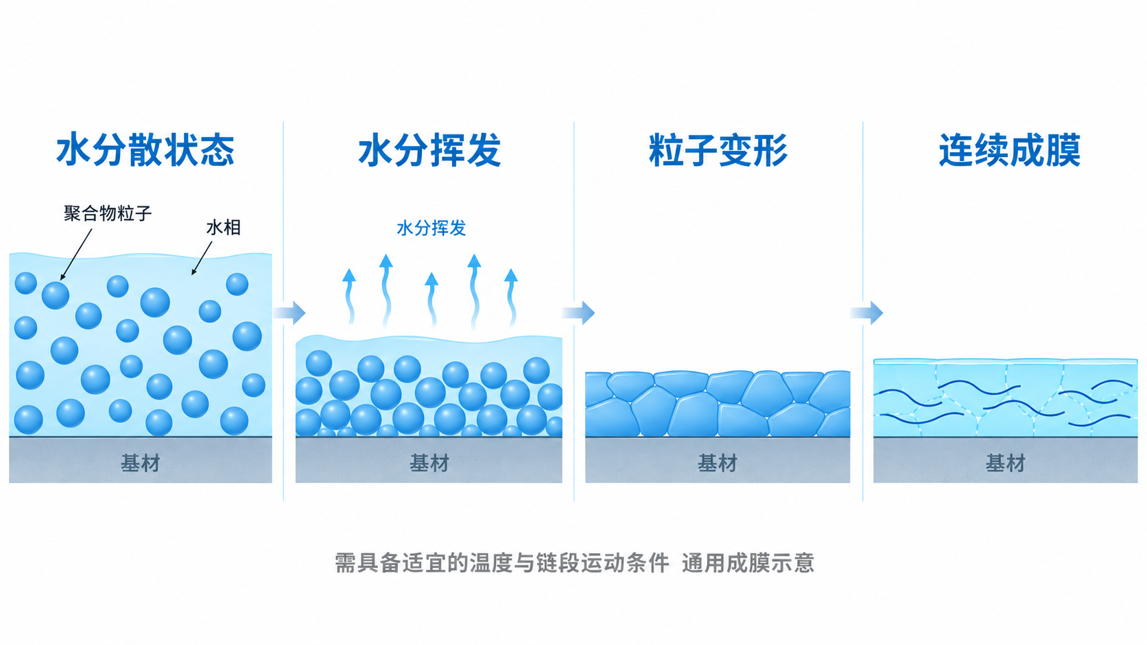
- Aqueous dispersion → water evaporation → particle deformation → continuous film formation.
- Polymer particles; aqueous phase; substrate.
- General illustration under suitable temperature and chain-mobility conditions. The stages can overlap; it is not a measurement of R-5610.
Water removal and film formation are interrelated
As water content decreases, particles move closer together and pack tightly. Under suitable conditions, they deform and fill gaps, while chain segments at points of contact move further and interdiffuse. The minimum film-formation temperature (MFFT) is the lower temperature limit for forming a continuous film under specified conditions. It depends on polymer composition, particle structure and formulation.[4]
Insufficient temperature, poor local water removal or restricted chain mobility can leave particle boundaries and micropores in the adhesive layer. Rapid surface drying does not necessarily mean that water has left the interior. The drying process should therefore account for coating weight, airflow, ambient humidity, substrate absorbency and the actual adhesive-layer temperature.
Systems that include a hardener also require coordination between film formation and reaction progress. Crosslinking helps establish the final network, but restricting chain mobility too early can hinder particle coalescence. Mixing ratio, pot life and drying conditions must be determined for the specific system. Minimum film-formation temperature, drying temperature and bonding activation temperature are different concepts and must not be substituted for one another.
Why interfacial voids can intensify white haze and light spots
An adhesive film may be transparent in its bulk yet show whitening after bonding. Common causes include insufficient local wetting, uneven layer thickness or air trapped between the adhesive and the substrate. Air and polymer have different refractive indices. Depending on the shape, size and number of defects, reflection, refraction and scattering can change the distribution of light.
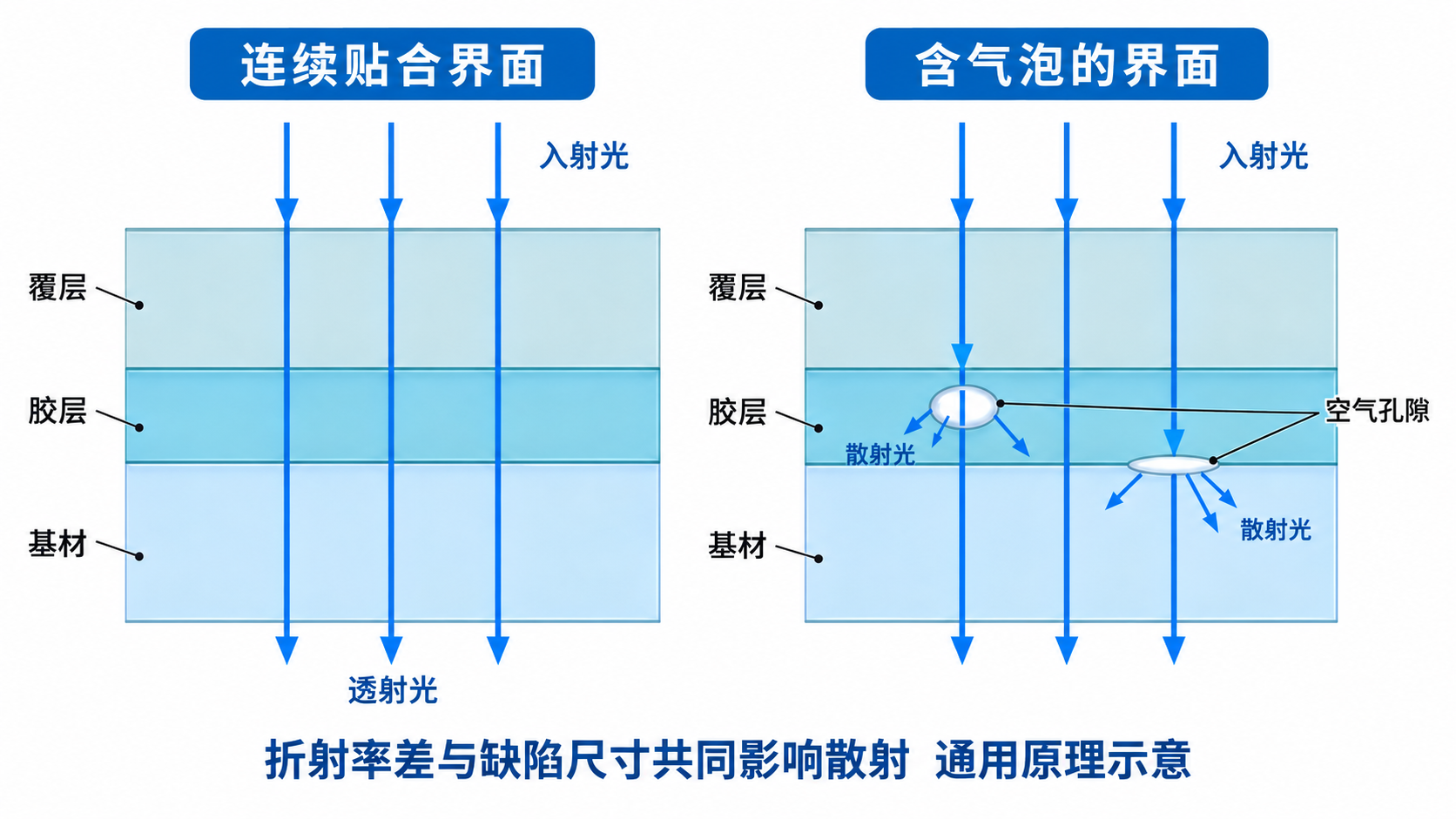
- Interface with continuous contact; interface containing air bubbles.
- Incident light; transmitted light; scattered light.
- Cover layer; adhesive layer; substrate; air voids.
- General illustration: refractive-index differences and defect dimensions jointly affect scattering. It is not to scale or a measurement of R-5610.
Refractive-index differences offer a starting point
At a flat interface between two homogeneous, transparent, nonabsorbing media, Fresnel reflectance at normal incidence can be expressed as:[5]
R = [(n₁ − n₂) / (n₁ + n₂)]²
Here, n₁ and n₂ are the refractive indices of the media on either side. This expression illustrates the importance of optical differences at an interface, but it is not a direct formula for bubble-induced haze or the transmittance of a composite component. Curved voids, rough surfaces and multilayer structures also introduce angular distributions and multiple optical interactions.
Process troubleshooting can begin by comparing an unbonded adhesive film with the actual composite, then checking whether anomalies are concentrated in adhesive build-up, wrapped edges, texture valleys or locally separated areas. Once interfacial voids are present, increasing light-source brightness alone will usually not resolve blurred patterns or localized white haze.
Film formation and interface control with RELANET R-5610
RELANET R-5610 is a high-transparency waterborne polyurethane adhesive for automotive interior wrapping and lamination. It is spray-applied and can form a relatively transparent film after thorough drying. For door panels, instrument panels and parcel shelves where light-colored substrates, decorative texture and consistent adhesive-layer appearance matter, process selection can be evaluated using the actual materials.
R-5610 can be used for manual wrapping, hot pressing or vacuum forming. Its application range includes laminating flexible materials such as PVC, back-coated IXPP foam, 3D Mesh and nonwovens to substrates including ABS, hemp-fiber board, PU sheet and flame-treated PP. Whether the resulting component can transmit light also depends on the optical properties of the skin, backing and other layers.
Typical process information
| Item | Published technical information for R-5610 |
|---|---|
| Solids content | Approximately 50% |
| Viscosity | Approximately 12,000 mPa·s (25°C / 6 rpm / S2) |
| Compatible hardener and mixing ratio | R-1060; R-5610:R-1060 = 100:5–8 by mass |
| Pot life after mixing | At a room temperature of 23°C, approximately 8 hours |
| Reference drying window | 50–70°C for 8–15 minutes |
| Activation temperature | Above 60°C |
| Time to maximum strength | Typical information: 72 hours; confirm when parts can move to the next operation based on holding performance |
| Substrate treatment | PP requires flame treatment; IXPP requires back coating |
The above is typical product information. Use the latest TDS for specific instructions and confirm the process window for the adhesive amount, equipment, material batches and environment. Typical values support process design; project acceptance limits should be defined by the customer specification or an agreed test plan.
Turn the theory into practical shop-floor records
At the specimen stage, keep spray atomization, gun movement and adhesive application weight per unit area consistent, then confirm drying and activation conditions. For specimens showing whitening or uneven light transmission, first examine adhesive-layer thickness, residual moisture, surface treatment and interfacial contact. Changing the hardener ratio or diluting on site alters the original process conditions, so film appearance and bonding performance should be checked again.
For more application information, see the RELANET technical article on transparent waterborne PUD. In actual projects, retain adhesive films, composite coupons and formed components together to distinguish the effects of the bulk material, bonding interface and component structure.
Products and further reading →
Define the process window through combined optical and bonding evaluation
Validation of light-transmitting interior components should cover both the initial condition and changes after exposure to service environments. An increase in haze generally indicates a change in scattering; yellowing is more closely associated with changes in visible-light absorption. They may occur together or separately, so transmittance, haze and color should be recorded independently.[6]
| Evaluation level | Suggested records | Question to answer |
|---|---|---|
| Substrate and adhesive film of specified thickness | Thickness, color, specimen preparation and conditioning; transmittance, haze and overall color difference | What is the optical baseline of the materials themselves? |
| Actual composite component | Actual layer stack, adhesive amount, treatment and bonding conditions; pattern edges, brightness distribution, white haze and bubbles | Does bonding introduce additional optical defects? |
| Bonding specimens | Initial holding performance, peel after conditioning, failure location and the corresponding test conditions | Is bonding capacity still adequate when the appearance is suitable? |
| Composite component after aging | Exposure according to project requirements for temperature and humidity, light or thermal cycling; repeat optical and bonding tests | Are appearance and interfacial stability maintained? |
When comparing specimens, keep thickness, light source, viewing distance and test method consistent. Methods for transparent, flat materials can be selected from the relevant optical standards. For textured, colored or strongly scattering interior composites, first confirm the scope of the standard, then supplement testing with component performance under the actual light source.[1]
Process optimization for a light-transmitting adhesive ultimately needs to produce several traceable results: a uniform adhesive layer, thorough and consistent film formation, continuous interfacial contact, and appearance and bonding performance retained after aging. Evaluating material combinations and processes for R-5610 around these results helps translate a transparent adhesive film into a consistent automotive interior appearance.
References
[1] ASTM D1003-21; ISO 13468-1:2019. Methods for measuring haze and total light transmittance of transparent materials.
ASTM D1003-21 · ISO 13468-1:2019
[2] Polymer, 2025, DOI 10.1016/j.polymer.2025.128951. Relationships between crystalline structure, refractive-index differences and haze.
DOI 10.1016/j.polymer.2025.128951
[3] Polymer, 1984, DOI 10.1016/0032-3861(84)90323-9. Light scattering and nonuniform structures in segmented polyurethanes.
DOI 10.1016/0032-3861%2884%2990323-9
[4] Yang and Craig, 2020, characterization of film formation in aqueous dispersions; Kwok et al., 2025, PUD film formation and chain diffusion; Aradian et al., 2000, interdiffusion and crosslinking.
PMC7066041 · DOI 10.1016/j.porgcoat.2025.109462 · DOI 10.1021/ma0010581
[5] Delft University of Technology, Interactive Optics. Fresnel coefficients and reflection at normal incidence.
TU Delft — Interactive Optics
[6] Polymer Degradation and Stability, 2003, DOI 10.1016/S0141-3910(02)00264-1. Changes in spectral absorption during aging of model polyester polyurethanes.
DOI 10.1016/S0141-3910%2802%2900264-1
Figures 2 to 5 are AI-assisted illustrations of general mechanisms. Structural dimensions are not to scale. They are not micrographs and do not represent measured microstructures of R-5610.